
If you’re not a Fusion 360 user, but you do use another parametric CAD program like SolidWorks or FreeCAD, you can keep reading. The principles are the same, even though the interface may be a bit different.
If you’re a user who has come from a direct modeling environment before moving to Fusion, you may have found the parametric features to be useless and hindering to your process. I know that’s how I felt, especially since certain tools don’t function the same and seem to have limits. Lately though, with the prospect of needing to create multiple variations of the same exact guitar model (different scale lengths, different neck pitches, different joints, etc), I started to wonder if I could make life a little easier.
Naturally, the first experiment was with a fretboard – and the results were excellent. I was able to create a project that serves as an automatic fretboard generator within about 30 minutes. I’ll include a walkthrough and a sample project file at the end for you to see what the fuss is about.
Parametric Modeling and Its Applications in Lutherie
For those who are new to the concept, parametric modeling relies on defined parameters and an editable timeline to allow users to return to previous points in their work history, make adjustments, and have the results generate from that point forward based on the changes. This is opposed to a direct modeling environment where any adjustments to previously generated objects will only affect the object in question.
For example – if a 5 x 5″ box is drawn in the sketch environment, then extruded into a 5 x 5 x 10″ 3-dimensional rectangle, the user can return to their sketch in their timeline and edit the parameters of the original sketch to 4 x 4″. This will then re-generate the subsequent extrusion and you’ll have a 4 x 4 x 10″ box sitting in front of you.
In Fusion 360 (and likely other parametric modeling software, I haven’t used others), you are able to create a list of user defined parameters. For instance, the parameter Scale could equal 25.5″, or BodyWidth could equal 13.5″. Combining defined parameters with Fusion’s various sketch constraints suddenly creates a world of interesting opportunities for a luthier wanting to make spec adjustments to a guitar model for a custom order or new variation they’d like to offer customers.
Since I myself am only just beginning to learn about the possibilities of a parametric environment, I’ll say this: I do foresee some tricky things to work out or that may not be compatible with the methods I’ve grown comfortable with already. But I intend to see how far it can be taken when it comes to offering a range of options for a single guitar/bass model.
For now, let’s just look at how to generate new fretboards on the fly with simple parameter adjustments.
Steps to Creating a Parametric Fretboard
Before getting to any 3-dimensional work, you need to decide on the basic specifications that will create a 2-dimensional sketch and the base parameters from which all future changes will be dependent on. Scale length is the first, from there number of frets, and then the widths of your nut and fretboard ends.
For simplicity’s sake, we’re just going to make one meant for an end-mounted nut, rather than a slotted Fender-style one. Here’s the process:
I. Define Scale/Fret Parameters
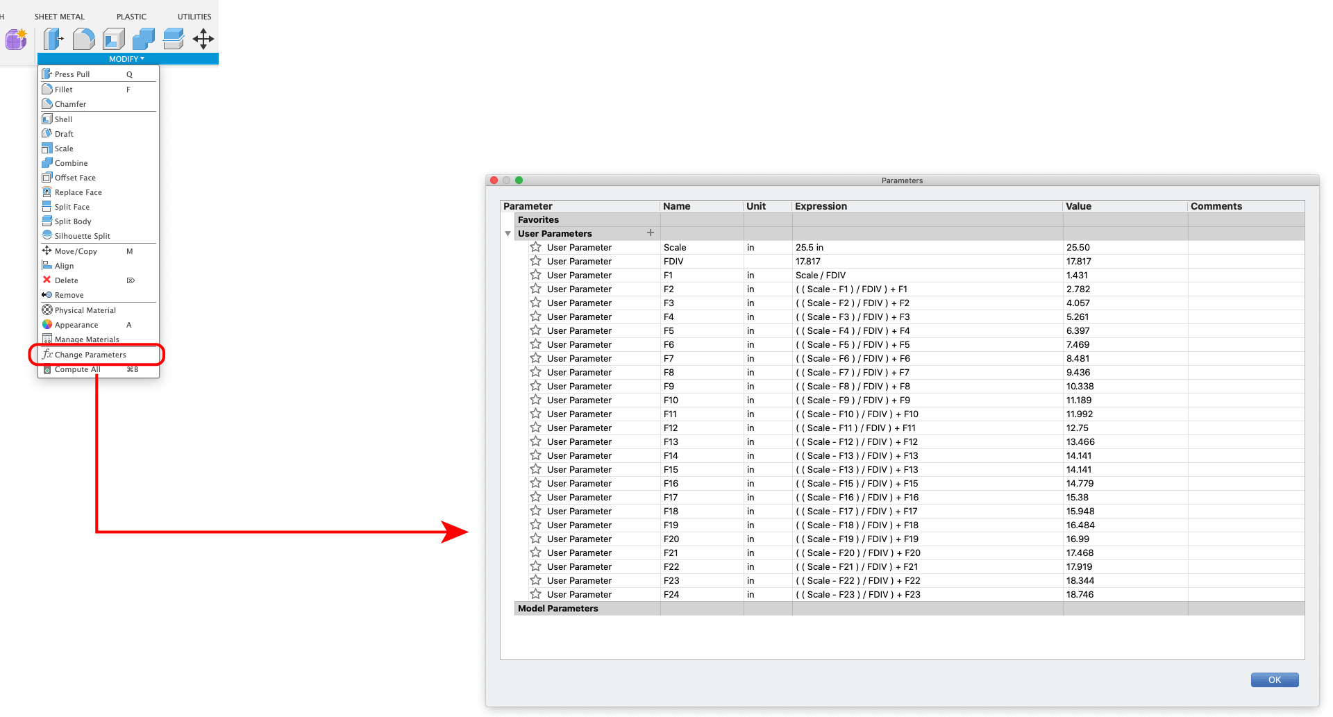
Create a new project using the parametric modeling environment in Fusion 360. Immediately head to the “Modify” dropdown and select “Change Parameters”.
You will note the very first parameter definition is the scale length. Here we are starting with a 25.5″ scale (note that the units are defined in the parameter, it’s perfectly acceptable to convert to mm).
The next thing you’ll notice is that there’s a parameter called FDIV (short for “fret position divisor”). The value is 17.817 and there are no units set (you can change the name to something else if you prefer). This is a magical little number that allows you to create formulas for calculating the fret positions. You can read about the process on BYOGuitar, or just take a look at this:
- 1st fret position (from nut) = scale length / fret position divisor
- 2nd fret position (from nut) = ((scale length – 1st fret position) / fret position divisor) + 1st fret position
- 3rd fret position (from nut) = ((scale length – 2nd fret position) / fret position divisor) + 2nd fret position
- and so forth
So, after giving my parameters handy little names I can remember like “Scale”, “FDIV”, “F1”, etc., I can create formulas that reference the preceding formulas like a chain. For this method, I felt it best to always be creating the distance from the nut rather than from the previous fret. This due to Fusion not allowing for offset lines to be offset points for new lines. You must use a line without any offset constraints – in our case, it will be a line we draw at the nut end of the scale.
II. Draw Your Scale & Fret Positions
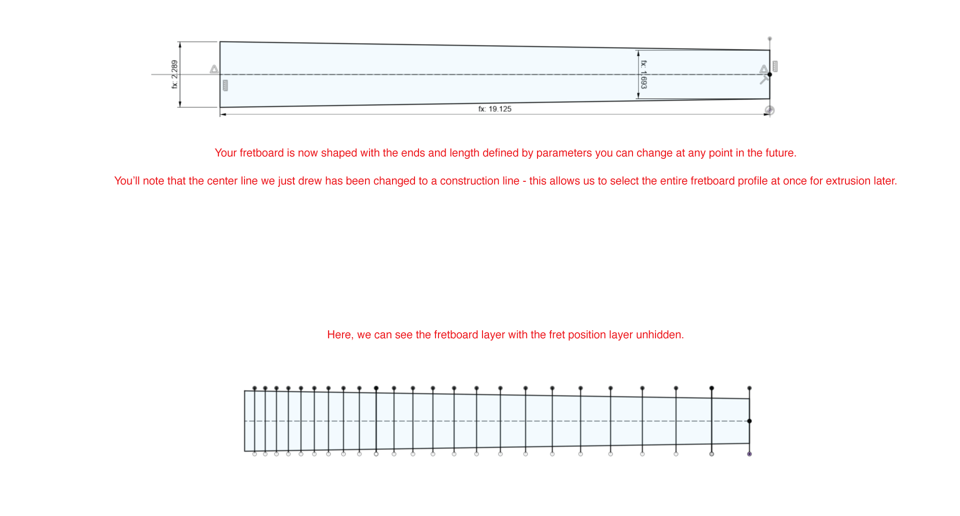
I like to keep my various components organized into separate sketches – bits and pieces can always be projected later onto new sketches if needed. For example – I always begin by making a sketch that contains just the scale length as a horizontal center line, with two 2.5″ lines at each end to mark the nut and bridge positions.

You will note that after the first 2.5″ vertical line is drawn, it is offset with the parameter “-Scale“. It is negated to send the line to the left and form the bridge marking line. Since Fusion does not allow us to offset lines that already have offset constraints, and we’d like to use our nut line to offset the fret positions and have the guitar oriented as a right-hand one, it’s best that we do it this way.
We can now close that sketch and create a new one for the fret positions.
All the subsequent fret position offsets will be negated as well:

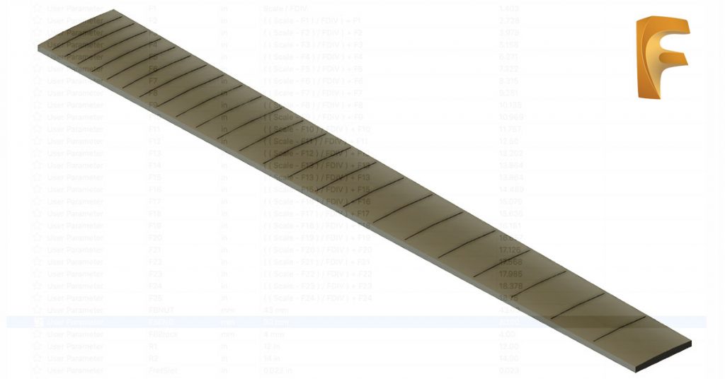
Now we have all our fret positions. If you think back to our formulas we entered in the parameter definitions, you’ll recall that each one references the one before it, right back to the scale length. If we were to go into the parameters now and edit the scale length, a chain of re-calculations would occur and the lines we drew for the scale length sketch and all of the lines on the fret position sketch would automatically reposition to create the basis for a new fretboard.
It’s important to note that the constraints you use in your sketches will still be taken into account – you can work strategically this way to ensure your adjustments create a desirable outcome.
So now we have two sketches: the scale length sketch and the fret position sketch. We will move onto a third one now.
III. Draw Your Fretboard
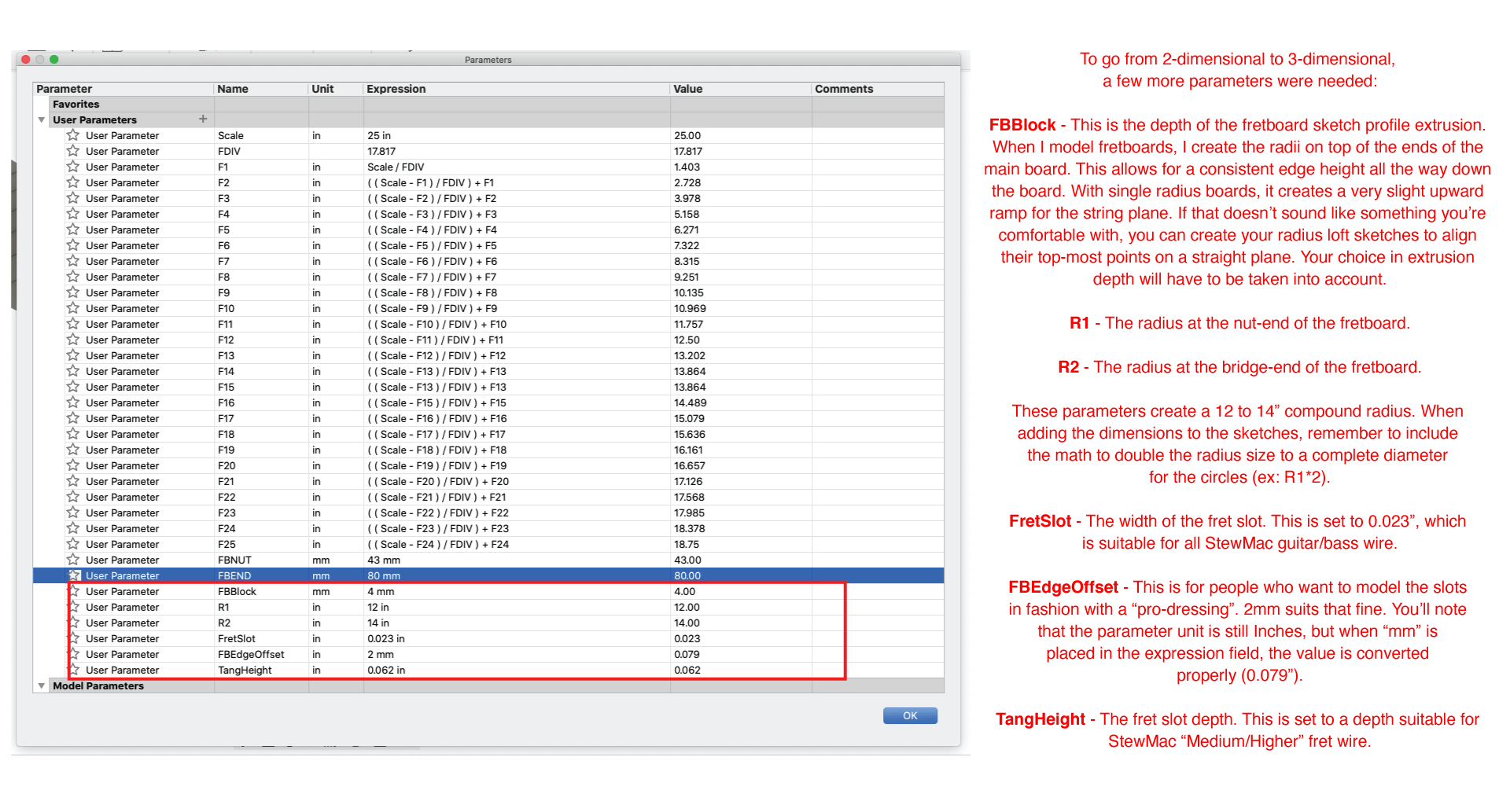
Before we do anything, let’s add a couple new parameters:
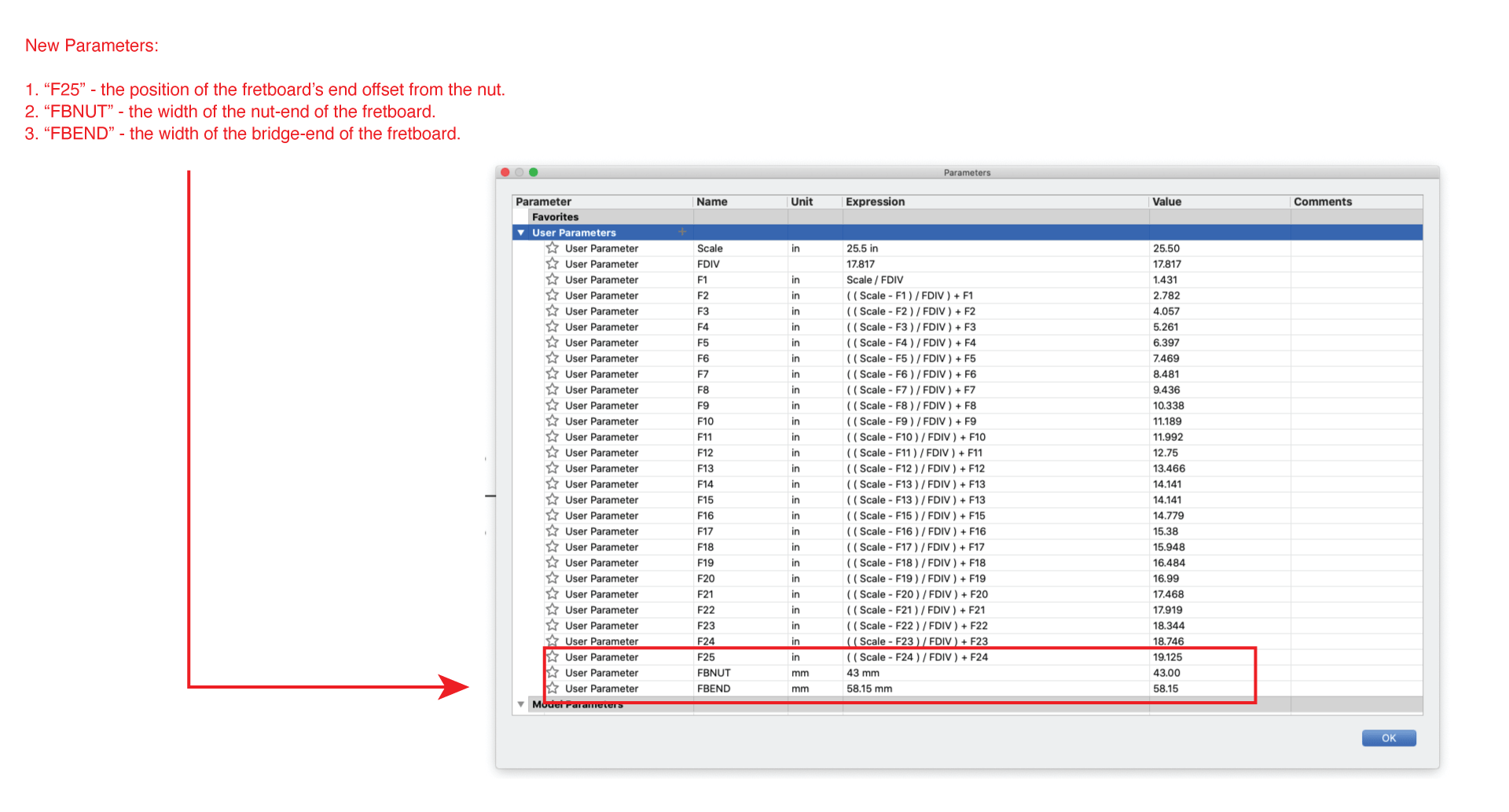
The first parameter added is called “F25” – it uses the same formula as the fret position formulas to define the location of the end of the fretboard relative to the nut. In other words, the overall length of the fretboard. If you prefer, you can change this formula to offset the end of the fretboard a specific distance from the last fret. For example: F24 + 0.25. This will just stick a quarter inch on after the last fret.
This parametric fretboard’s initial dimensions are based on an Ibanez Wizard variant (here’s a comprehensive spec list of Ibanez necks). So the parameters for the widths of the nut and fretboard end are 43mm and 58.15mm, respectively. Remember to set your parameter units correctly.
Now we can move on to drawing the fretboard ends and connecting them. Create a new sketch, hide the fret positions sketch and leave the scale lines sketch visible:
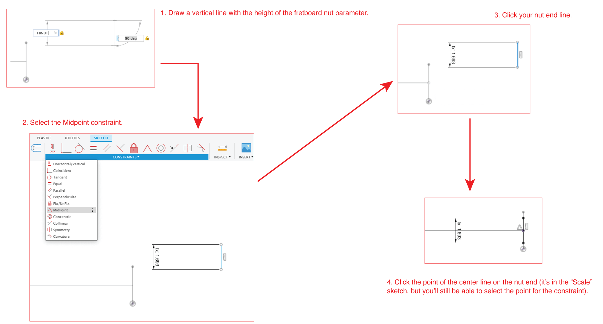
Now we need to place the fretboard end line – your first thought may be to just offset the nut line we just placed, but unfortunately we can’t. Fusion will not allow us to add a new size constraint to an offset line that already has a size constraint.
So to do this, we’ll create a center line from the nut line out to where the fretboard end is meant to be using that F25 parameter we added. Then you’ll do the same thing we did for the nut-end line, this time using the FBEND parameter and the midpoint constraint on the other end of the line we just drew:

Now you can simply use the standard line tool to connect the points and admire your fretboard shape:
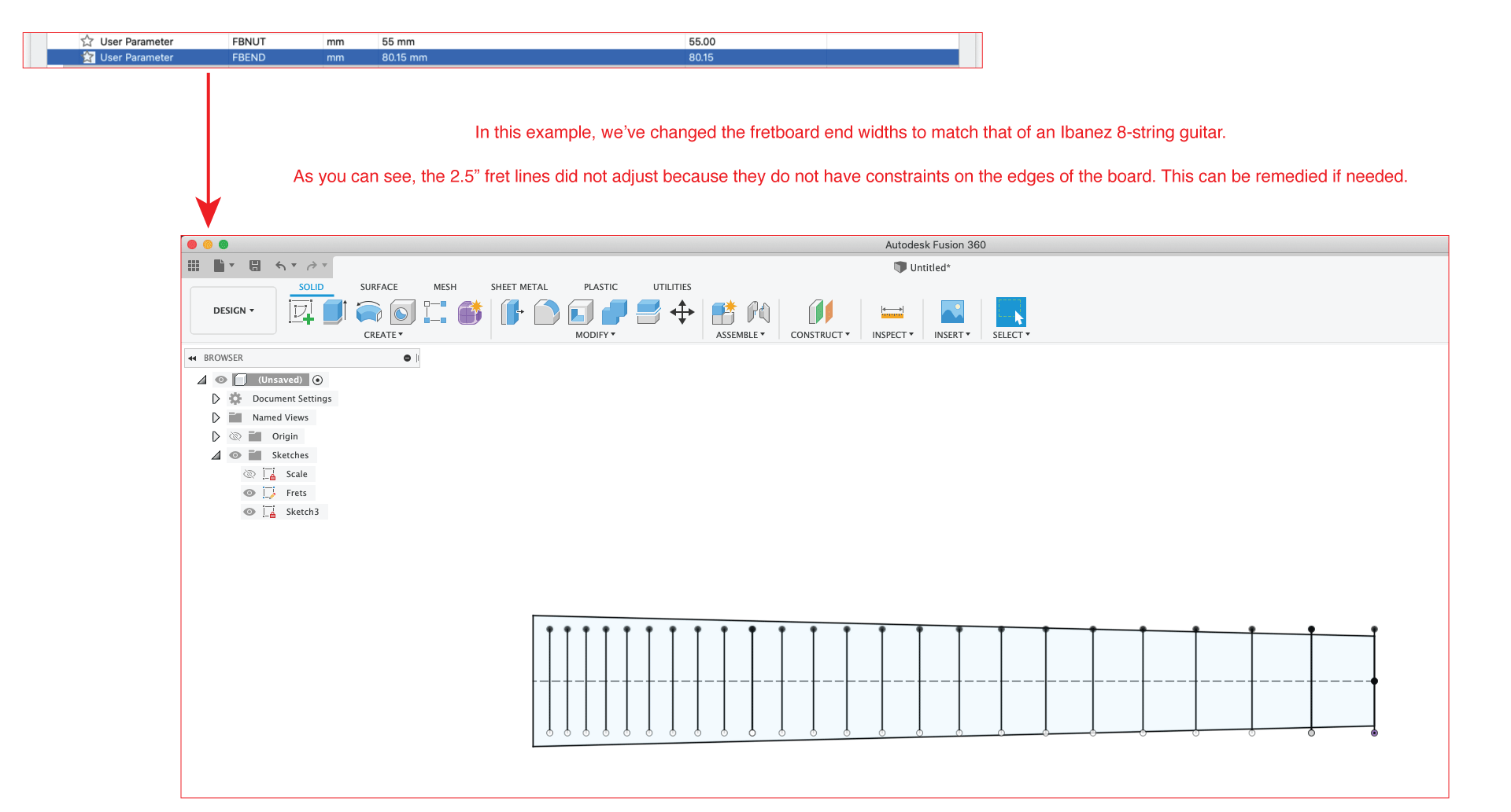
IV. Testing the Parametric Function
Now you should have three layers: the scale lines, the fret positions, and the fretboard shape lines. If you’ve followed along, you can now edit your parameters and have all three sketches adjust to match your new specifications. To do this, you simply open your Parameters window again and edit the field(s):

Here’s another example to better illustrate things:
Download the Fusion File Here
If you haven’t fully understood the steps, or are just feeling lazy, the project file for these parametric fretboard sketches are available for download.
If you’re interested to see how it works 3-dimensionally, continue on!
How Does This Work 3-Dimensionally?
So far, splendidly. I have to re-iterate that this fretboard project is my first foray into parametric modeling, so I have yet to build on the system and make a fully parametric guitar. I anticipate a few headaches, but let’s just take a look at what we’ve got so far:
I won’t cover the entire process of the extrusions/lofting since it’s covered here. I will say that 3 new sketches were created:
- A sketch for the fret slots drawn with center-oriented rectangles constrained to the center of the fret position markers with the “FretSlot” parameter set as the width, and 5″ height on each to ensure they will more than cover any widths. This sketch also projected the edge lines of the fretboard shape sketch and offset them inward using the “FBEdgeOffset” parameter to create slot profiles that don’t run all the way to the edges.
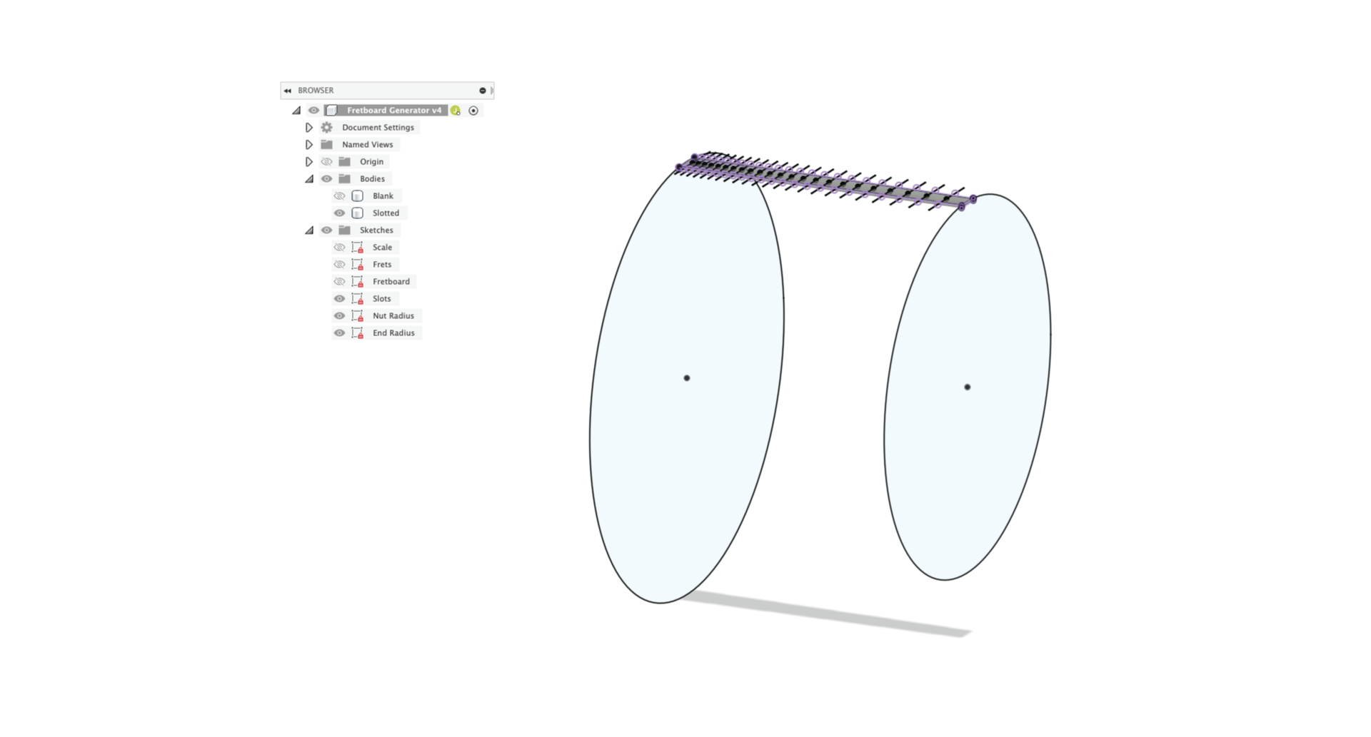
- A nut-end radius sketch – this was created after extruding the main fretboard shape downward using the “FBBlock” parameter. The sketch was made on the plane of the nut-end face. That face was projected and a circle was drawn using the parameter “R1*2”, then constrained to the top left and right points of the projected face.
- A bridge-end radius sketch – same as above, but using the parameter “R2*2”
The radius profiles were lofted to each other and joined with the main fretboard body, then a copy of that body was made and hidden before fret slots were made (never hurts to keep a blank around). Here’s a quick look with relevant sketches unhidden:
And here’s the results of a fully slotted model before and after parametric adjustments:
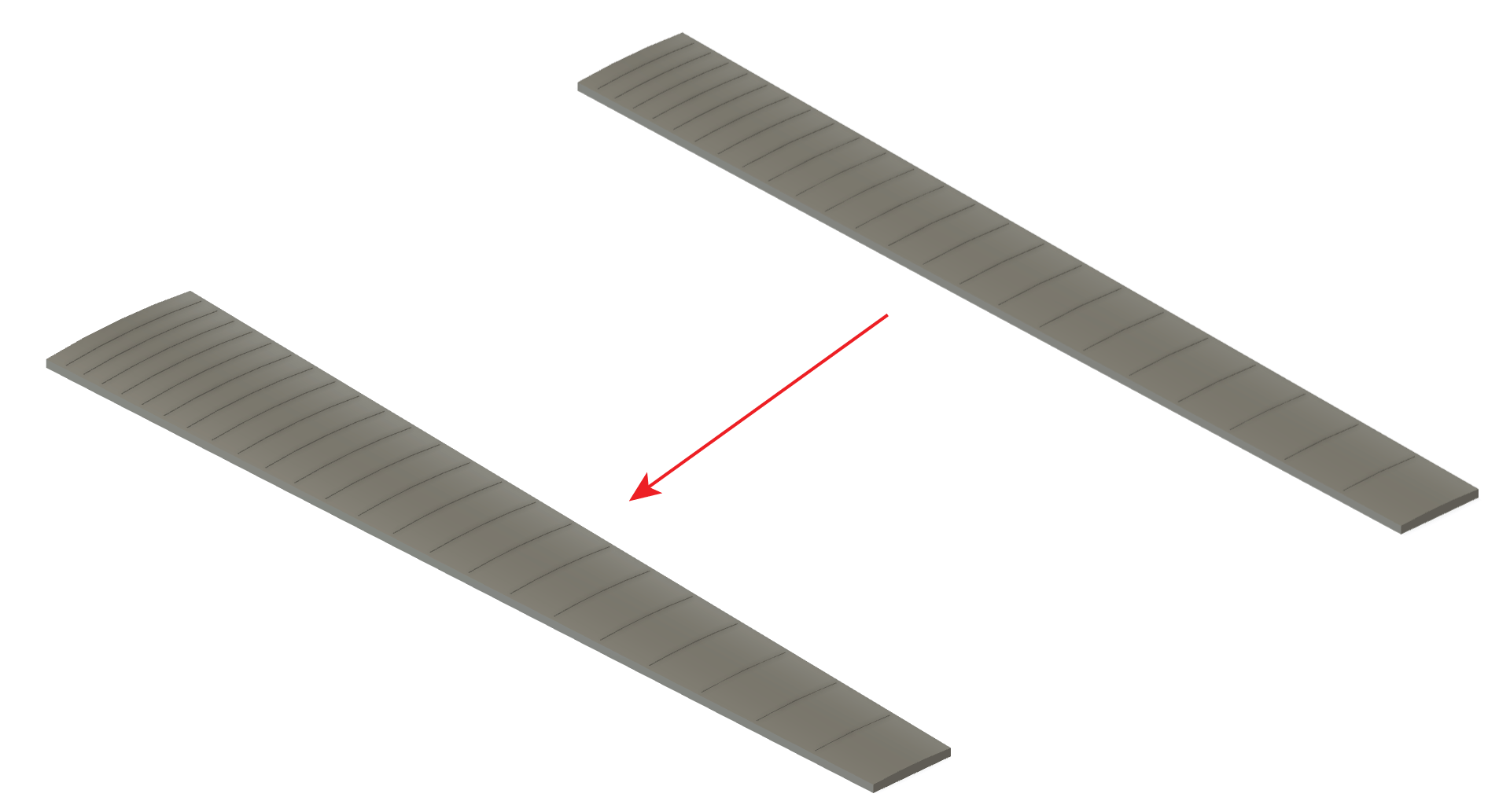
So simply by changing two parameter fields, I was able to generate a fully-functional fretboard for an 8-string guitar. If I were to change one more text field, it could be lengthened with all the fret slots in place for a baritone scale. Adjusting two more fields means I can change to any radius I like, compound or otherwise.
This is all happening in a matter of seconds.
What Are the Applications of Parametric Guitar Design?
As someone who has resisted the parametric modeling environment for so long simply because it’s unfamiliar, I have to say there’s most definitely a lot of potential. These fretboards, for example, could have included little radiused corners at the end or fret markers that could all be adjusted parametrically.
For anyone who is focused on manufacturing parts, or constantly having to model for custom orders, the potential should be pretty evident. Things like pickup rings & routes, bridge post spacing, ferrule spacing, tuning machine holes – they can call be done parametrically on the fly.
The challenge is having the foresight to ensure that all of your parameters, formulas, and constraints follow a hierarchy when attempting to create more complex parametric setups for an entire neck or body. It’s certainly worth exploring more if you’re like me and have neglected parametric modeling for years and suddenly want to catch up.
Update: Video Walkthrough of the Process
As it turns out, a guy named Austin Shaner created a Youtube video that outlines the entire process of creating a parametric multi-scale fretboard. He does things a little differently, such as the radius and fret position calculations. I was actually very pleased to see his method for cutting fret slots was much more efficient than drawing each slot. Definitely worth watching.
